2025-26 · Our CanSat
ZeroSat V2.
Our 2025–26 CanSat: a whole satellite in the volume of a soda can. Keep scrolling and we'll take it apart.
01 / 05
First, the can.
This is prototype v2. Every structural part was printed together in PLA — 4 hours 36 minutes for the lot.
02 / 05
Three boards. Stacked.
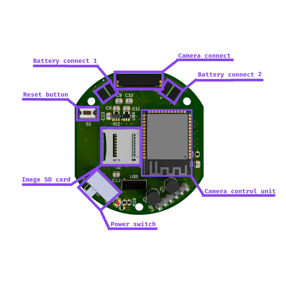
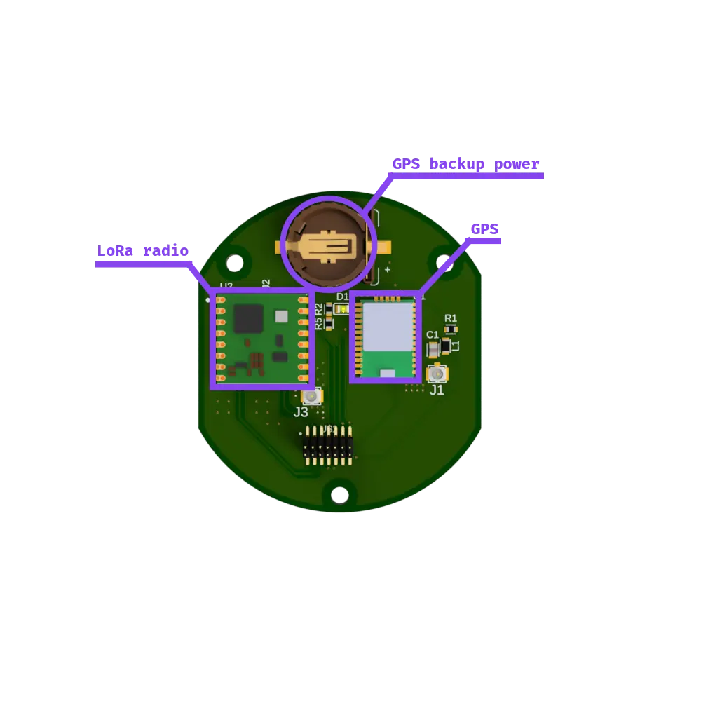
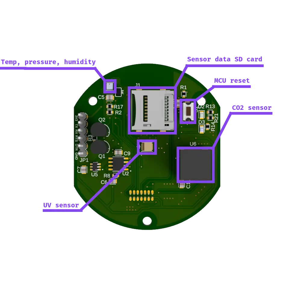
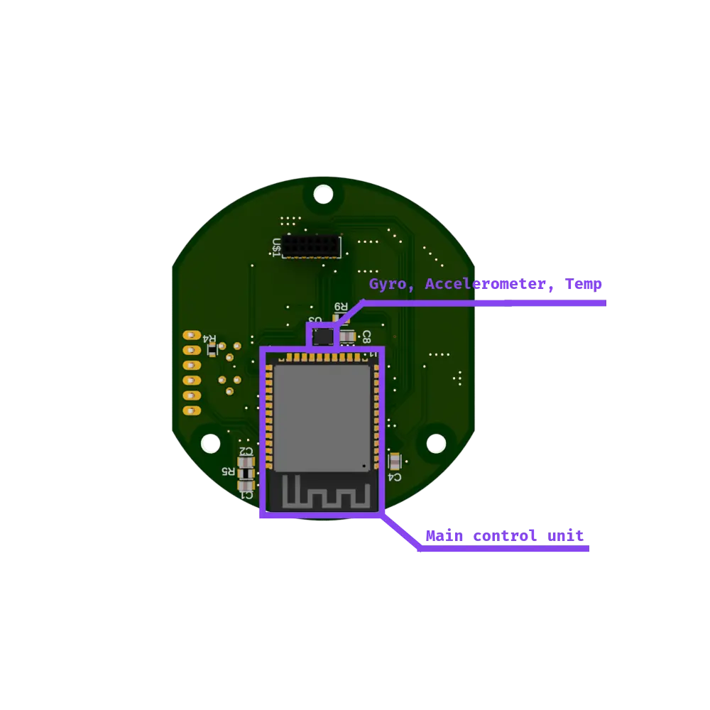
Main, comms and camera. All three designed by us, stacked on standoffs like a very small layer cake.
03 / 05
Holds together. Mostly.
Camera mount at the bottom, battery holder above it, a board mount on top, and two side arms bracing the stack.
04 / 05
Every part has a job.
CO₂, UV, temperature, pressure, humidity, motion, GPS, a camera — and LoRa to phone home.
05 / 05
And back in the can.
66 mm across. The rest of this page explains how it works.
Loading 3D model
- Lid
- printed PLA
- Main board
- ESP32 · CO₂ · UV · T/P/RH · IMU
- Comms board
- LoRa radio · GPS
- Camera board
- camera MCU · image SD card
- Board mount
- Side arms
- Battery holder
- Camera mount
- looks straight down
Shell
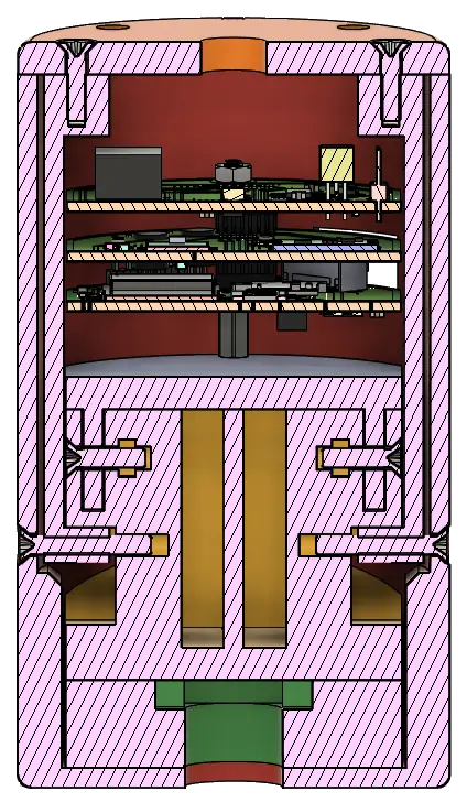
The structure of our CanSat consists of a 3D printed housing that keeps the electrical components safe, in place, and connected to the parachute. Inside the shell are blocks designed to house specific components and connect to the PCBs. We use polycarbonate, known for its high heat and impact resistance, and iron where plastic wouldn't be strong enough due to size constraints.
Electronics
We have sensors for UV radiation, three temperature sensors, three humidity sensors, barometric atmospheric pressure, a gyroscope, acceleration, and an air quality sensor.
We also have a camera, which captures images of the ground that we can correlate with valuable data.
The sensor telemetry and the first few pictures are transmitted to the ground station via LoRa.
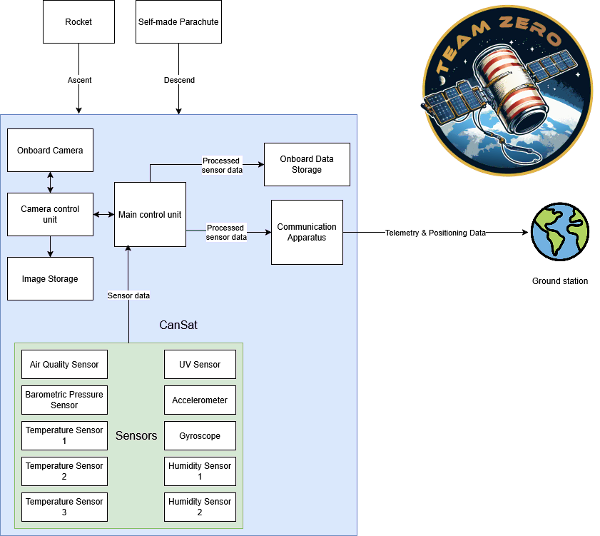
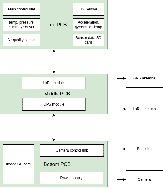
Other important components that are not sensors include the LoRa radio and two SD cards — one for saving captured images, the other for backing up sensor telemetry. We also have a GPS to keep track of the location of our device. For microcontrollers we chose the ESP32: one is the main control unit, and the other is the strongest ESP32 we could find for the camera, since it needs plenty of RAM to save 4K pictures to an SD card while aiming for video frame rates.
Software
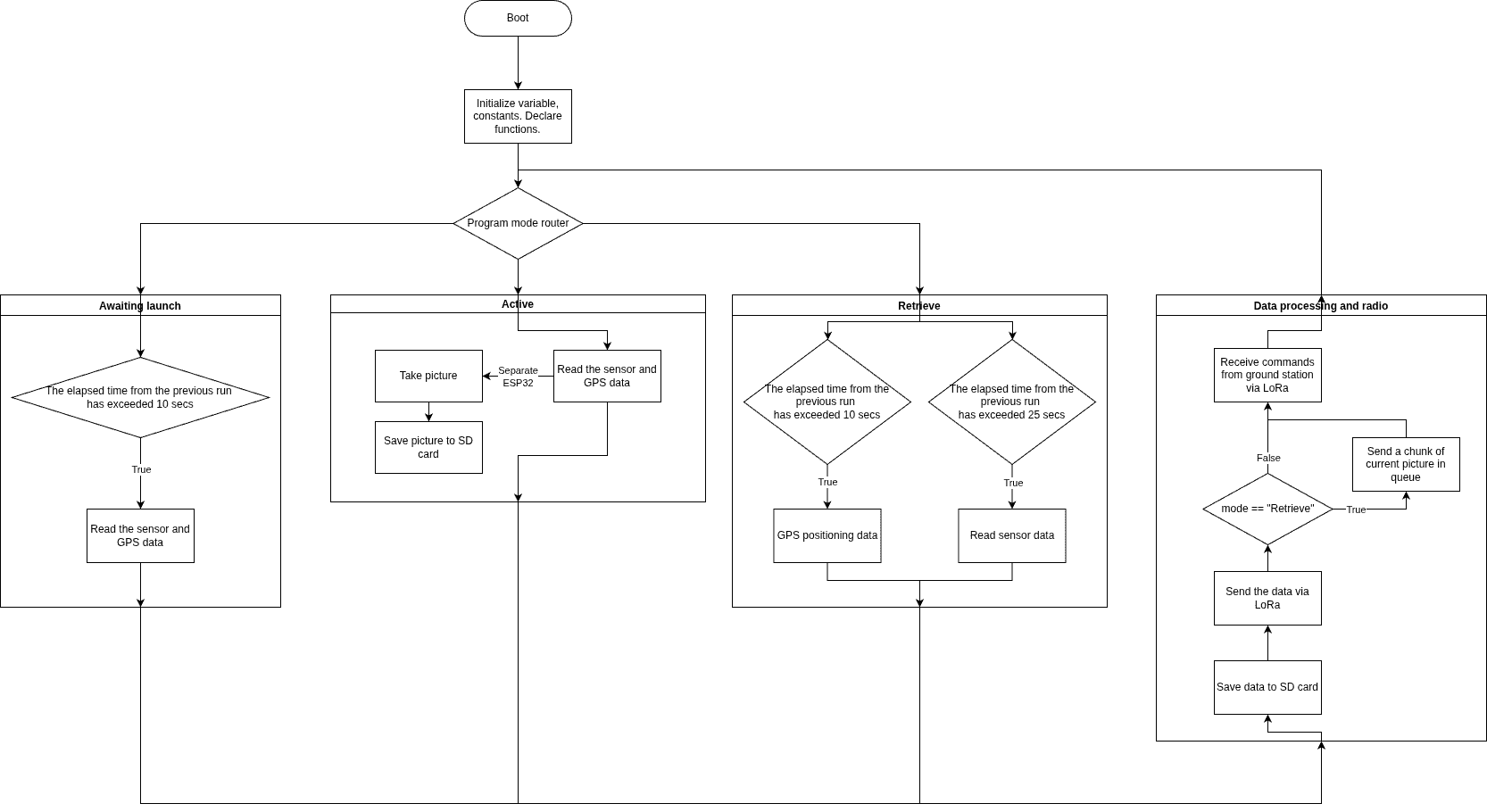
The following flowchart shows how our program flow works. It has three modes, which can be switched manually from the ground station.
Awaiting launch — sensors and GPS are read every 10 seconds.
Active — all sensor data is read as fast as possible, and the camera takes pictures.
Retrieve — sensors are read rarely, but GPS location is sent every 10 seconds so we can find the CanSat easily.