
2024-25 · Our CanSat
ZeroSat 1.
Our first CanSat, built for the 2024–25 competition. Keep scrolling and we'll take it apart.
01 / 05
Shell off.
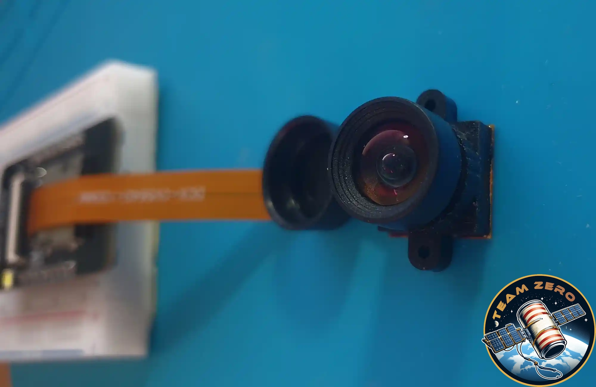
A 3D-printed housing. The cap at the bottom carries the camera and the temperature–humidity sensor.
02 / 05
Two boards, back to back.
Our own PCBs face outwards with the 18650 cell tucked between them. The kill switch pokes out of the top.
03 / 05
Modules. Lots of them.
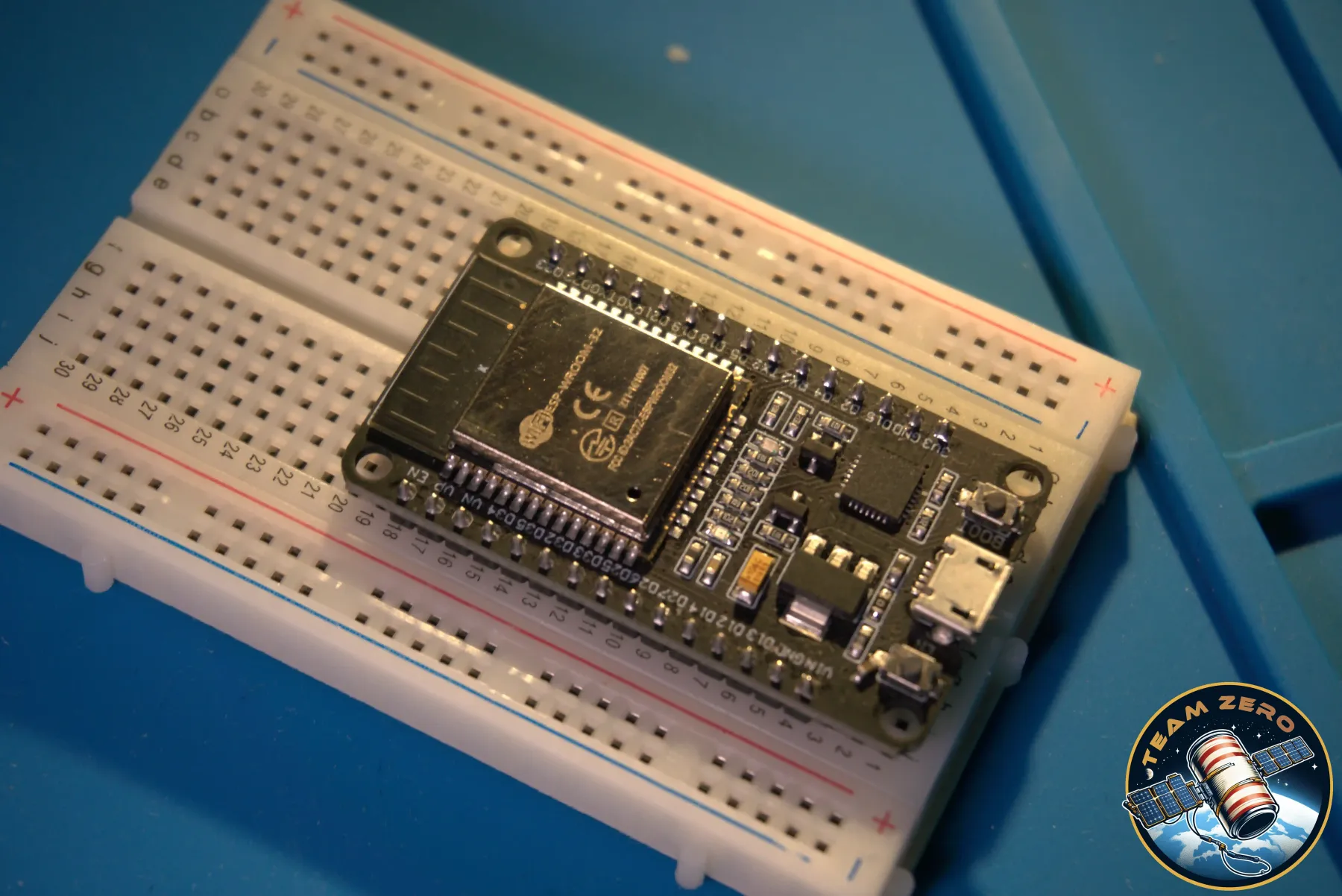
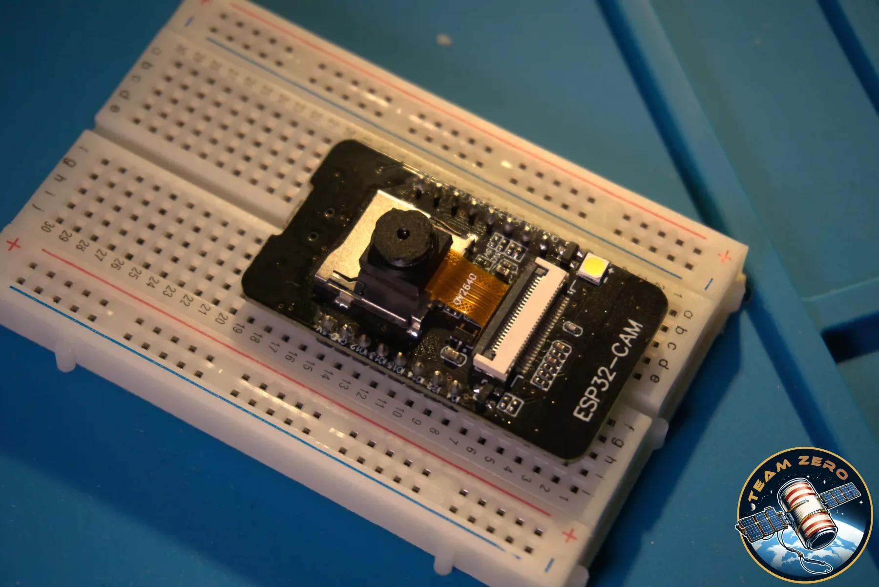
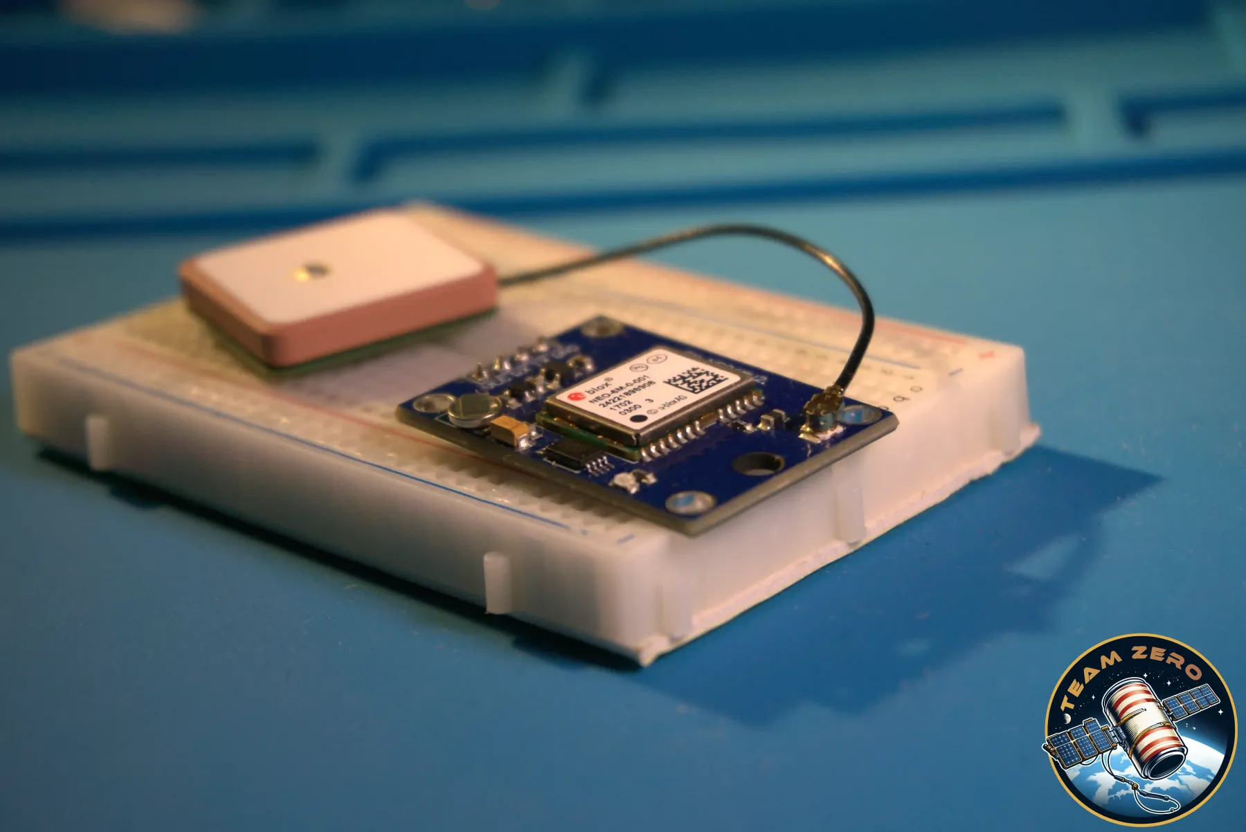
One ESP32 runs the show, an ESP32-CAM runs the camera, and GPS, LoRa, microSD and a GY-91 plug straight in.
04 / 05
Every part has a job.
UV, temperature, humidity, pressure, orientation and acceleration — logged to the card and radioed down over LoRa.
05 / 05
And back in the can.
The rest of this page explains how it works.
Loading 3D model
- Bottom cap
- camera + DHT11 mount
- Battery holder
- Kill switch
- cuts all power
- PCB, front
- 40 × 80 mm
- PCB, back
- 40 × 80 mm
- 18650 Li-ion cell
- GPS
- position for recovery
- ESP32-CAM
- camera controller
- LoRa radio
- telemetry downlink
- ESP32 DevKit
- main controller
- microSD
- on-board data log
- GY-91
- motion + pressure
Shell
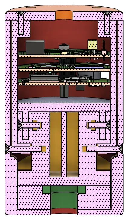
Our CanSat's shell is made of 3D printed plastic. The frame holds our custom-designed PCBs and has holders for the shut-off switch, battery, and UV sensor. The cap attached to the bottom of the housing holds the camera and the combined humidity and temperature sensor.
Electrical components
With our sensors we currently measure UV radiation, temperature, humidity, air pressure, orientation, and acceleration. We also have a camera, which has a separate controller.
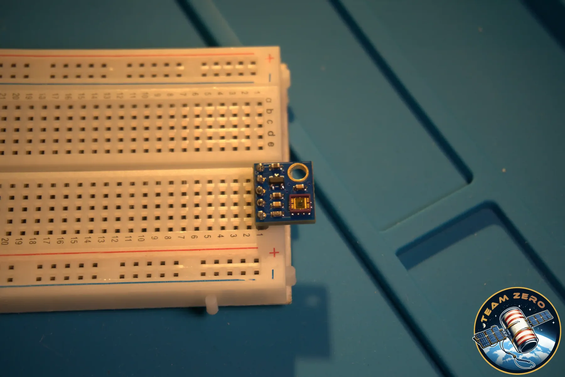
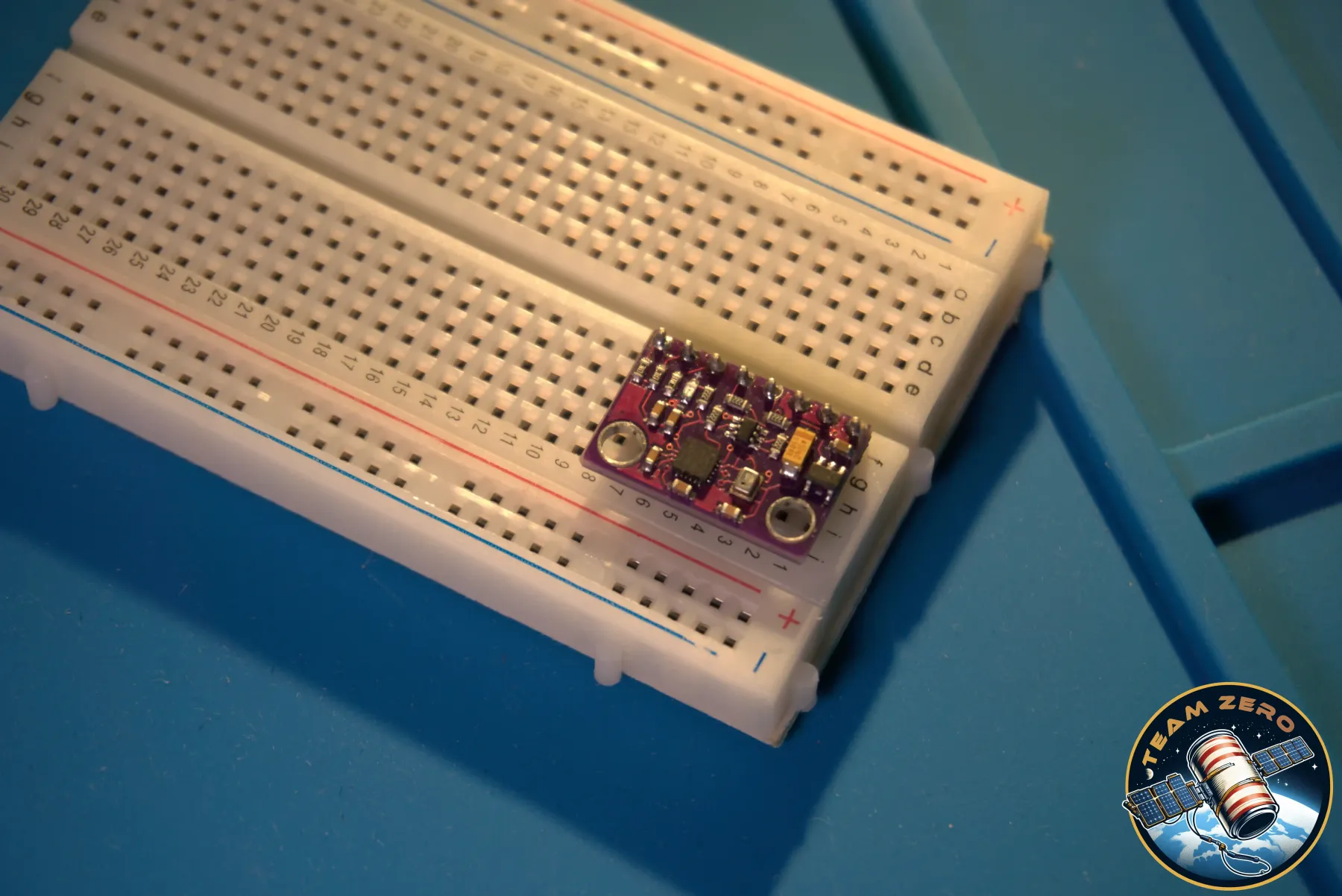
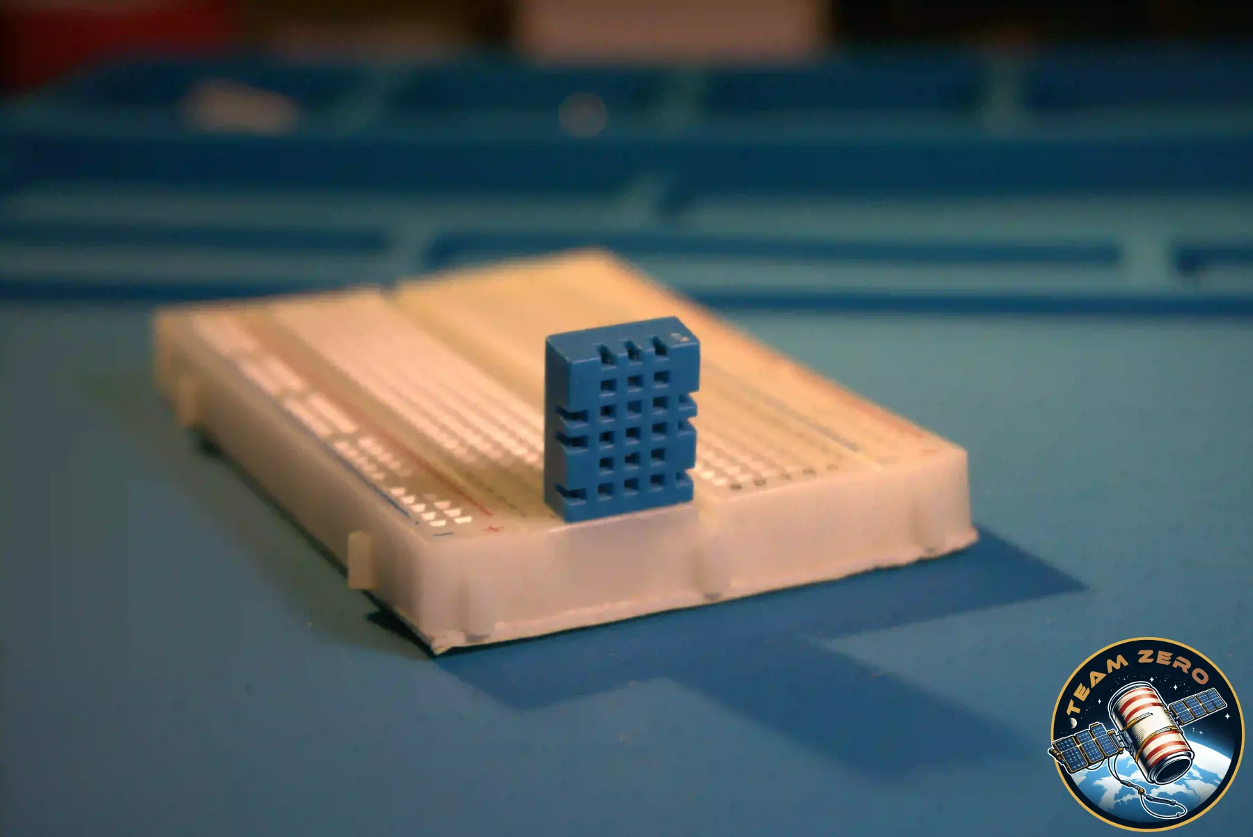
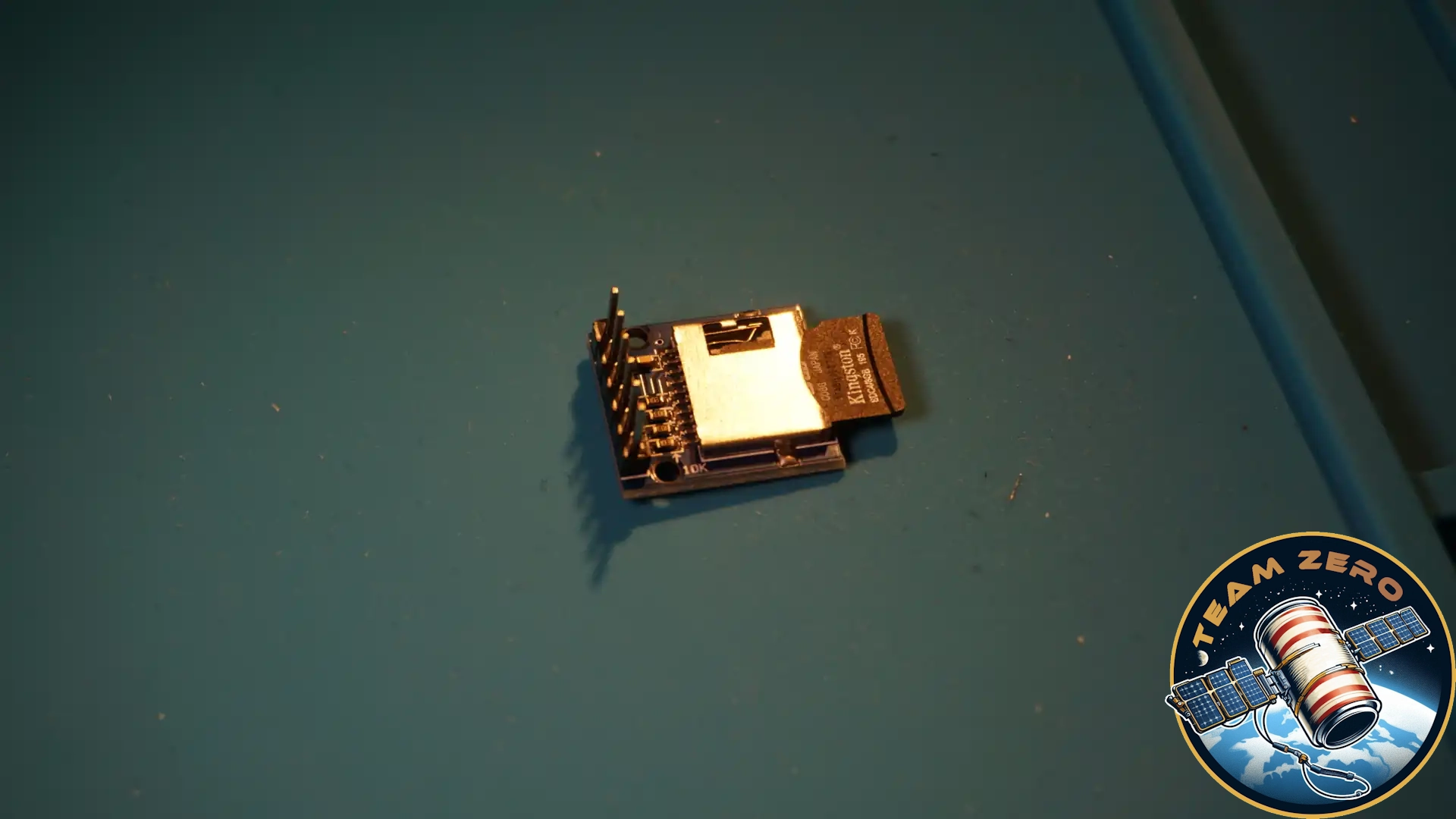
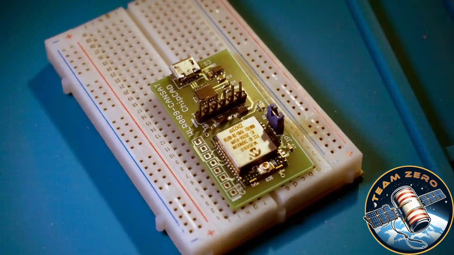
Other very important components for the mission are the LoRa module to send data down to the ground station, an SD card breakout board to save data locally, and a GPS to help retrieve the CanSat and track where it is descending. We also save the gathered data with the main ESP just in case, and lastly we have a microcontroller for the camera.
Software
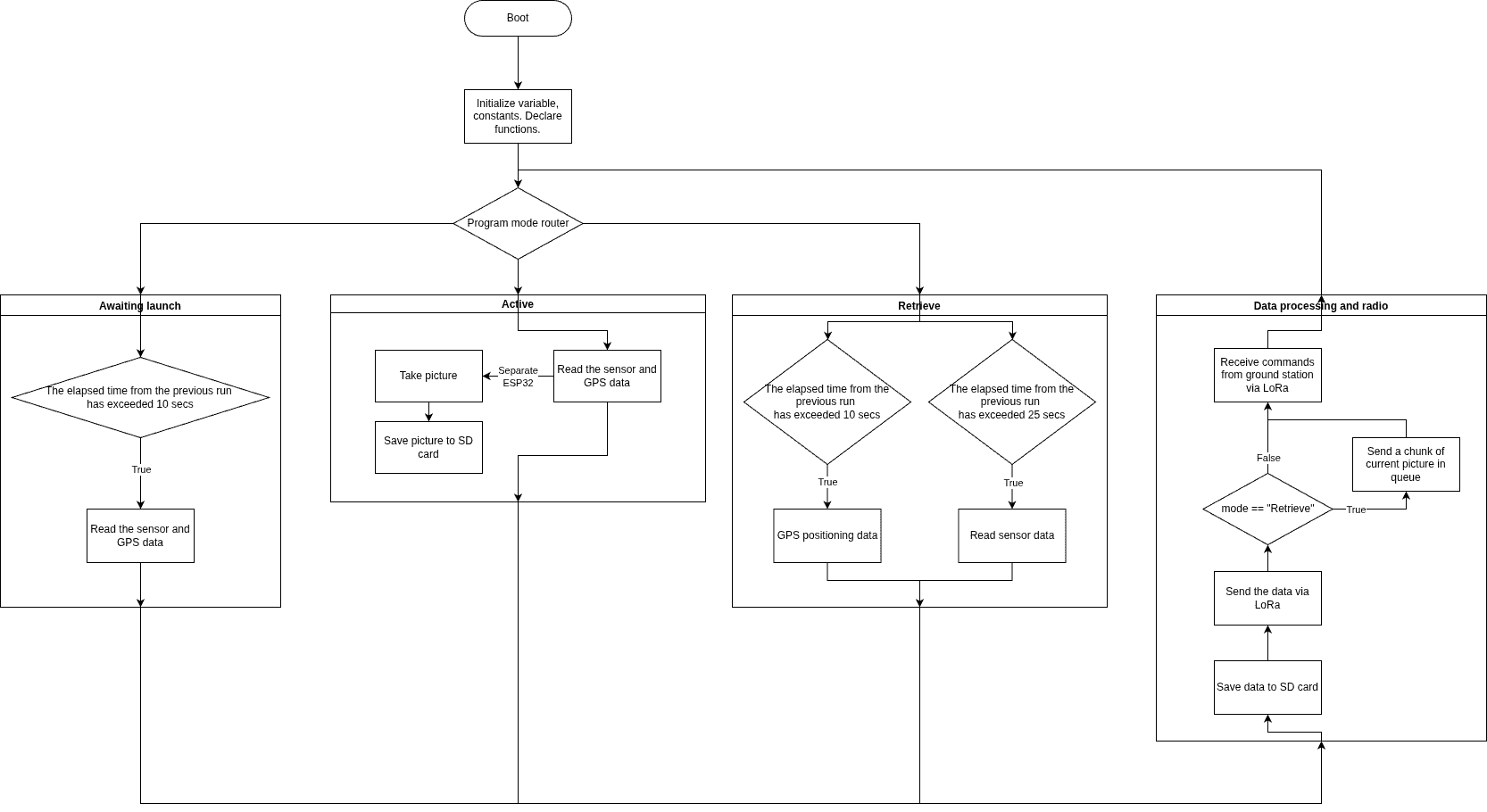
The following picture shows the flow diagram of the general overview of the CanSat's software. It is fairly straightforward. Some of the less obvious processes:
— The ESP-CAM is turned on and off by a FET, controlled by the main ESP.
— The time since the last picture was taken is tracked by the main ESP, by reading a pin that goes high when the ESP-CAM takes a photo.
— The power mode is controlled by us from the ground station: we send a byte sequence that changes the "power mode" of the main ESP once it receives the signal via the LoRa module.
Mission goal
The aim of the mission is to tell whether an area is habitable, based on what we can measure with the electrical components. The reasons for choosing this mission are described in the Ambitions section on the team page.
How can we determine if an area is habitable?
— UV levels show how dangerous the sun is for human skin.
— Pictures of the terrain tell us if the area can be used for agriculture or living quarters.
— Humidity is one of the most important factors for a planet's liveability, since we need water to survive.
— The CanSat's acceleration in different directions tells us wind direction and speed.
— Temperature cannot be too high or too low, for obvious reasons.
— Big differences in air pressure can cause headaches, vomiting, or even brain swelling, which can be fatal, so it must stay at a normal level.